Friday 24 April 2020
Wednesday 22 April 2020
slip casting ceramic paper bag vase, mug // brutalist sphere tree house, Giuseppe Perugini // sculpture generator
https://www.google.com/search?q=how+to+do+slip+casting+for+a+paper+bag?&tbm=isch&source=iu&ictx=1&fir=NjdWAK5yM_j8vM%253A%252CH9KlJwv6WjnqNM%252C_&vet=1&usg=AI4_-kSHkQDNGdIzLu3RJ_-8cGUKpShGPg&sa=X&ved=2ahUKEwir9crBp_roAhUDz4UKHU76DpoQ9QEwDHoECAUQBw#imgrc=NjdWAK5yM_j8vM:
slip casting ceramic paper bag vase, mug
https://www.youtube.com/watch?v=q4qbvahedBM
Casa Sperimentale - The story of the house by Raynaldo Perugini, Architect
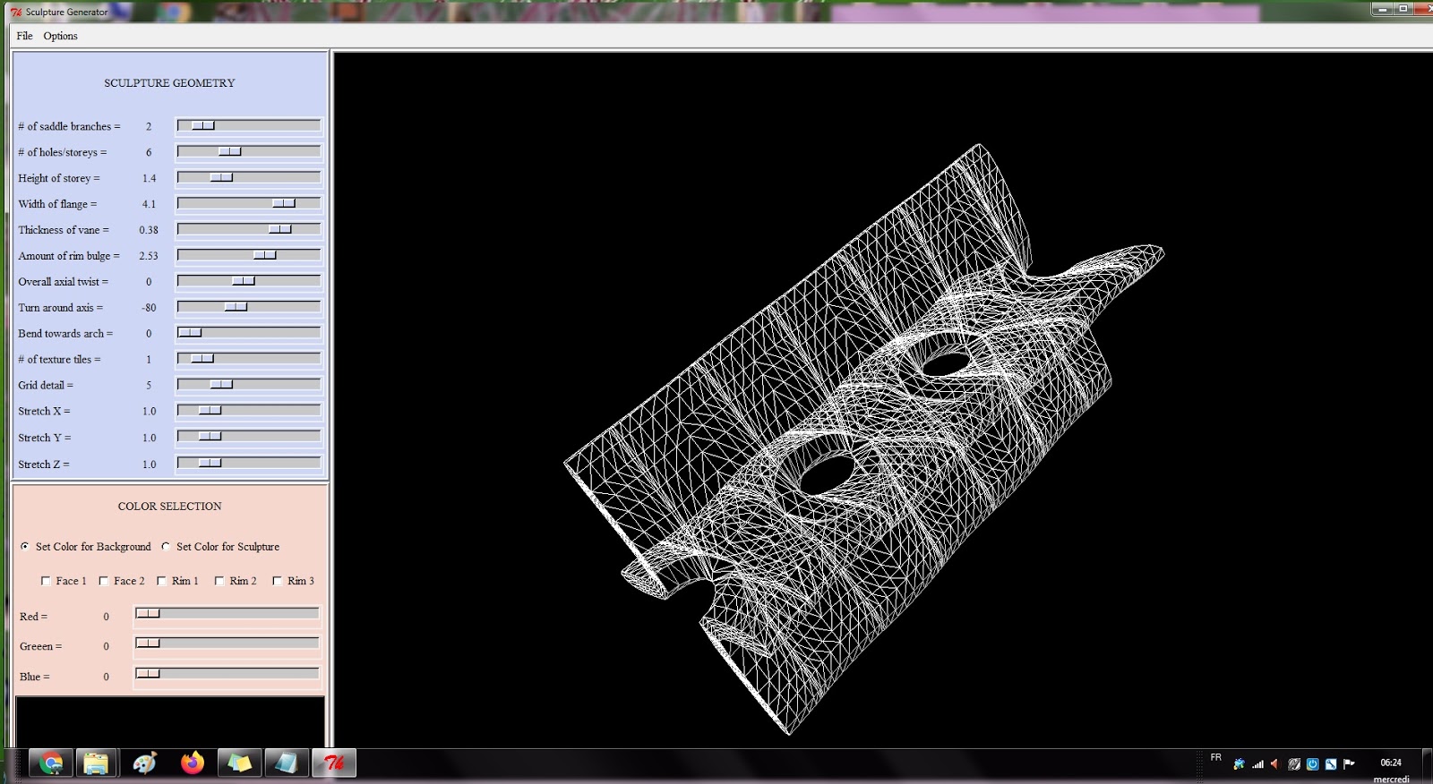
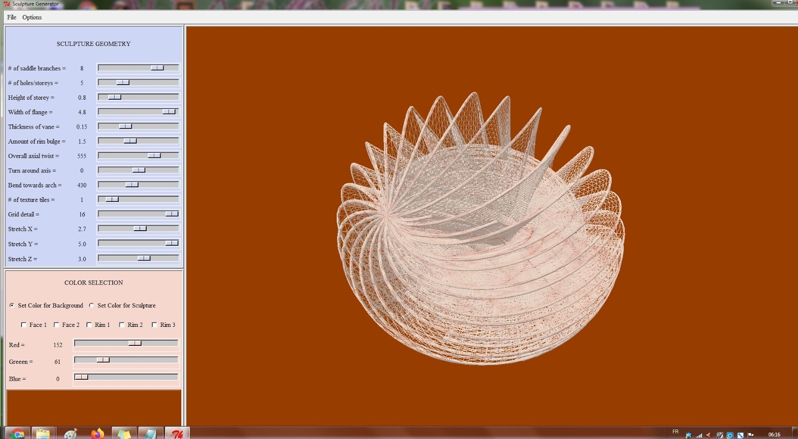
https://people.eecs.berkeley.edu/~sequin/SCULPTS/scherk.html
http://3doc.i3dconverter.com/ file format converter
https://people.eecs.berkeley.edu/~sequin/SCULPTS/sculpts.html
sculpture hyperbolic planes generator
slip casting ceramic paper bag vase, mug
https://www.youtube.com/watch?v=q4qbvahedBM
Casa Sperimentale - The story of the house by Raynaldo Perugini, Architect
https://people.eecs.berkeley.edu/~sequin/SCULPTS/scherk.html
http://3doc.i3dconverter.com/ file format converter
https://people.eecs.berkeley.edu/~sequin/SCULPTS/sculpts.html
sculpture hyperbolic planes generator
Sunday 19 April 2020
ceramic shell, pla lost casting // silicone figurine mould
https://www.youtube.com/watch?v=1VNy6QuakxY
Lost pla ceramic shell 2
Mold Making & Casting Tutorial: 73-20 Figurine Mold
Saturday 18 April 2020
http://www.thingiverse.com/thing:21074
https://wikifactory.com/+unfold/claystruder-2-auger
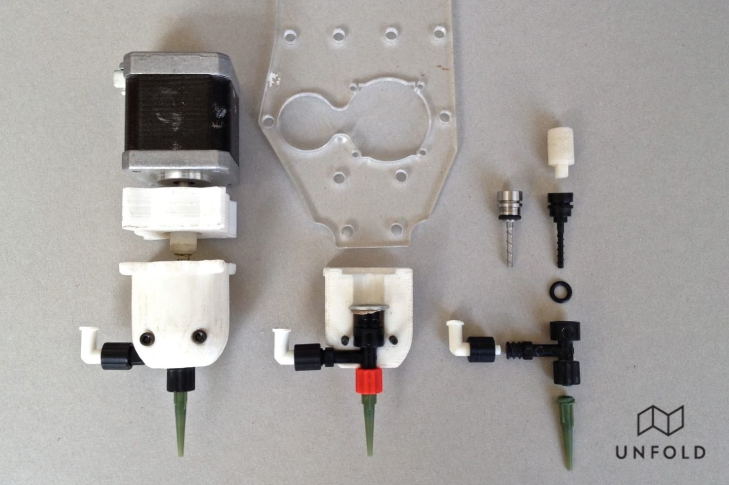
https://wikifactory.com/+unfold/claystruder-2-auger
Claystruder 2 (Auger)
Repost of the 2012 Claystruder 2, a prototype for a paste extruder that is build around a fairly lowcost, off-the-shelf disposable auger extruder. This design is a testbed and not meant as an elegant design.
Last activity
19 hours ago ●
Contributions
6
Open Issues
Friday 17 April 2020
burnt out pla model for casting at 650°, pla burns clean
https://www.youtube.com/watch?v=HVgPM1ojyLw
slowly heat up to 650° burnt out pla model to make a plaster mould
myfordboy.
myfordboy.blogspot.com
https://www.youtube.com/watch?v=l638qR0Y6YE
metal casting, how to make green sand
slowly heat up to 650° burnt out pla model to make a plaster mould
myfordboy.
myfordboy.blogspot.com
https://www.youtube.com/watch?v=l638qR0Y6YE
metal casting, how to make green sand
Thursday 16 April 2020
Wednesday 15 April 2020

slip casting with ready-made objects
Slip casting with ready-made objects
Often I see very beautiful mass produced objects and I think why not give it a more permanent presence with porcelaine? Make it precious.
For example this plastic egg, that I see as a v beautiful tea bowl.
So, I learnt to make a plaster mould at the ceramic studio of a colleague, and did a small series of tea bowls in my spare time.


3d printed Models for casting or
Direct firing, depending on the model and the material.
sample: "HighFive cup"
Sunday 12 April 2020
3d-gaja-multitool-maxx - from Poland
https://3dprint.com/77037/tytan-3d-gaja-multitool-maxx/
10 diff extruder cnc heads
10 diff extruder cnc heads
Scara arm printer MO (reviewed by Robotdigg) original design by Qing Xin

https://youtu.be/TylvaVnbHRc
Scara Arm 3D Printer operation video https://www.youtube.com/watch?time_continue=49&v=TylvaVnbHRc&feature=emb_logo
Scara 3D Printer
The firmware is not Open Source, it's Not Windows10 compatible.
User end Software, Guides and Video Demo are provided.
Features:
1. All-metal structure, durable;
2. The dual-arm bearing structure, high strength, seamless, good accuracy, low resistance, spike all the simple structure without bearing arm;
3. Gear - belt transmission, high speed ratio, spike gear motor; Reason: The gear motor is a gear shift, there is a gap of 1MM gear and shift relatively small.
4. Small footprint, large print size;
5. On the desktop, such as flat print directly, no heat beds, energy saving afraid burns.
Techinical Parameter:
Printing Area:200*200*150mm
Machine size:350*320*400mm (Metal body)
Packaging size: 400*400*450mm
Power:220V 12V Support battery print
XY Accuracy: 0.5mm
Layer Accuracy:0.05-0.4mm
Printing Speed: 100mm/s
Printing Filament: 1.75mm pla
Profile style: STL/OBJ/GCODE
Operating System: XP,WIN7,WIN8,WIN10,MAC
Printing Method: PC connection
Operating Software: CURA repetier-host
Testing the Robotdigg SCARA Arm 3D printer
A colleague spotted this Robotdigg SCARA Arm 3D Printer which sells at just US$280 + shipping and import VAT. As I was working on SCARA printer support in RepRapFirmware, this seemed an ideal low-cost platform to test it on. So we bought one.
In this blog entry, I describe my experiences with this printer as it arrived and what I needed to do before I could try printing with it. A subsequent entry will describe the conversion to Duet Ethernet electronics.
Unboxing

The printer was supplied fully assembled, wrapped in cling film and surrounded by lots of foam polystyrene in a large cardboard box. After unwrapping the cling film and vacuuming up copious quantities of tiny foam polystyrene beads, it looked like this.
Supplied in the same box was a USB cable and a 12V 5A power brick accepting 100-240V AC input. The mains lead supplied was very short and had a US-style 2-pin plug, but the mains inlet to the power brick was a standard figure-of-eight one, so I was able to substitute a longer mains cable with a UK mains  plug.
plug.
 plug.
plug.
Also supplied was a bag containing two spanners, two spare brass nozzles, and four Allen keys.
Construction
The printer is constructed from black 2040 aluminium extrusion, finished with blue plastic trim in the slots and black plastic end caps. The base comprises two pieces of extrusion in a T-shape, held together by a large aluminium pulley that is screwed into the top of both of them. At the centre of the pulley is a large rotary bearing – the proximal joint – and the rest of the printer apart from the extruder drive is supported by this bearing. There is a rubber foot under each of the 3 extremities of the frame.
The vertical axis is another piece of 2040 extrusion with a threaded rod at each side clamping it to the bearing at the bottom. There is a large metal eye at the top.
The proximal joint is driven by a stepper motor connected to the large pulley by a 10mm wide MXL belt. The motor rotates with the rest of the printer, while the pulley remains stationary.
Attached to one side of the vertical extrusion is a linear rail. A slider on the rail bears a 2040 horizontal extrusion, which forms the proximal arm. A stepper motor and leadscrew provide vertical drive to the proximal arm.
 The distal joint is at one end of the proximal arm, and it is driven by a stepper motor at the opposite end of the arm through 2 stages of belt drive reduction using 10mm MXL belts. The distal arm is 2020 extrusion. One end is bolted to the distal joint, the other carries the hot end.
The hot end is similar in construction to the E3Dv6 but it is not a clone because the dimensions are different – for example the heatsink is 25mm diameter instead of 22mm. It is clamped in place, allowing the nozzle height to be adjusted by several mm. The top has the same 16mm diameter as an E3Dv6, however the E3D hot end is shorter. There is no print cooling fan or Z probe.
The extruder drive is mounted on the back end of the base frame T and serves as a counterweight. It is a metal direct drive extruder with adjustable spring tension. The Bowden tube goes from there through the eye at the top of the printer and down again to the hot end. It is a whopping 900mm long.
The printer does not have a bed. This is not unusual for a SCARA printer, because the area reachable by a SCARA arm is often large and has an irregular shape. You could clamp a glass plate to the desk just in front of the printer, or stick blue tape directly on the desk and print on that as I did.
Electronics
 The electronics enclosure is a black acrylic box, mounted on the side of the vertical axis so it rotates with the printer. There is a 40mm cooling fan blowing air into the box on one side, and exhaust holes on the other. Power and USB connectors are at the top.
The electronics is an ATMEGA2560-based board that I didn’t recognise, with space for 5 plug-in driver modules (4 populated). There is a bed heater output even though this printer (like many SCARA printers) has no heated bed, and 3 other mosfets for heaters and fans.
None of the cables going to the electronics is labelled.
The three stepper motors whose labels I was able to read are type SL42STH40-1684A. The label on the 4th motor was obscured, but the motor looks the same as the other three.
Firmware
The Robotdigg web site states The firmware is not Open Source, it’s Not Windows 10 compatible. But I connected it via USB to my Windows 10 computer anyway. The printer showed up as Silicon Labs CP210x USB to UART Bridge in the COM port listing within Device manager.
I loaded Pronterface and was able to connect to the printer at 115200 baud. The firmware announced itself as Marlin 1.02, Last Updated: Jun 24 2016 08:03:14 | Author: (Pavlo Gryb, sscara). So it’s definitely open source firmware, even if Robotdigg doesn’t supply the source to this particular build.
The good
- This printer came fully-assembled rather than in kit form
- It is built almost entirely from off-the-shelf parts, so it is easy to modify
- A basic tool kit and 2 spare nozzles were included
- The finish was smart – black extrusion, with blue trim in most of the slots, and black end caps
- The bearings seem to be solid and free from play
- A proper linear rail and leadscrew have been used for the Z axis rather than the cheaper option of a wheeled carriage and threaded rod
- The large eye at the top makes it easy to move the printer
- The hot end has been trouble-free so far with no tendency to jam
- When I first ran filament through the hot end, some red filament was extruded before my white filament came though, so the hot end had evidently been tested
- This printer was inexpensive, costing less than many Prusa i3 clones.
The bad
Base T-frame
The major mechanical issue with the printer as I received it was that the T-shaped base frame was far from rigid. I think was caused by a combination of inadequate design and minor damage during shipping. As mentioned above, the two base pieces of extrusion that for the T are held together only by being screwed to the large pulley, using 2 screws for each of the 2 pieces of extrusion. This did not create a rigid joint. The cheeks of the pulley had become slightly bent, and the hot end and nozzle wobbled up and down alarmingly.
 In order to put a screwdriver to the screws securing the pulley to the extrusion, I had to remove the electronics box. This box was secured to the vertical extrusion using two M5 screws and T-nuts in the slot. Unfortunately the T-nuts were not the sort with springs to keep them in place when the screws are removed, so they fell down the slot. However, the screws securing the electronics were evidently too long, because they had left witness marks in the extrusion. So to was a simple matter to use Blu-Tak adhesive to hold the T-nuts in place and lined up with the witness marks when I needed to replace the electronics (having added an extra washer under each screw head).
It was also apparent from witness marks that the large pulley had slipped along both extrusions. There was a gap between the end of the extrusion forming the shaft of the T and the extrusion forming the bar. I was able to loosen the screws, slide the extrusions along the pulley (closing up the gap in the process) and tighten the screws, which removed most of the wobble.
 However, in my opinion this method of fixing the two extrusions together is unsatisfactory. So I purchased two 2020 right angle brackets and some 10mm M5 screws and M5 slot nuts. I fitted the brackets between the arm and the step of the T, one on each side. I also replaced the Philips head screws securing the pulley to the extrusions by cap head screws, to permit better tightening and to allow the screws to be tightened or even removed using an Allen key, without having to remove the electronics box again.
Hot end fan and duct
On applying power to the printer, the hot end fan ran very noisily. Investigating this, I found that the front of the fan duct was bent into a concave shape when it was clipped on the heatsink. This meant that the screw holes for the fan were no longer parallel, which meant that the screws securing the fan to the duct were distorting the frame of the fan so much that the blades were contacting the frame. Loosening the screws provided a temporary fix.
Z leadscrew binding
When I sent a G28 ‘home all’ command, the printer successfully homed the proximal and distal joints, but failed to home the Z axis because the carriage got stuck before it reached the homing switch. This was due to poor alignment between the thrust bearing at the bottom of the leadscrew, the leadscrew nut attached to the proximal arm, and the Z motor at the top – caused the carriage to bind as the leadscrew refused to bend. Once again, due to the use of Philips head screws instead of socket head, I had to remove the electronics to gain access to one of several screws that defined the alignment of the thrust bearing with the vertical extrusion. I loosened a few screws, homed Z to allow the thrust bearing to find its natural position, and tightened the screws again. After that I was able to exercise the printer through its full Z range.
The ugly
Backlash
With the printer homed and still powered to energise the motors, I tested how far I could move each arm against the force provided by the motor. To my surprise, I found that both have significant movement. The distal arm is worst, it takes very little force to move it by 3mm. When I do this, I can see that the belt that drives the distal joint is moving relative to the small pulley driving it. The belt is taught. Under magnification, I can see that the teeth of the belt (labelled B154MXL) are narrower than the spaces between them – as they should be on an MXL belt. However, on the pulley the flats between the teeth are at least as wide as the flats at the top of the teeth – if anything, slightly wider. Clearly, the tooth profile of the pulleys is not the correct MXL profile. It’s also generally noted that MXL belts have significantly more backlash than the more commonly-used GT2.
The proximal joint gives 1.5mm movement at the end of the proximal arm with a little force applied – better than the distal joint, but still far too much. The larger radius of the large pulley probably accounts for the improvement. Again the belt is taut and I can see the belt moving relative to the small pulley, indicating once again that the tooth profile does not match the MXL belt.
I could attempt to fix this by purchasing new small pulleys, however the only suppliers I found were Chinese and there is no guarantee that they will have the correct profile. A better option may be to change them for GT2 pulleys and belts.
Some of the photos published by Robotdigg show two springs added, one on each arm, to pull the arm in a particular direction – for example, the first two photos here. So it’s clear that Robotdigg had problems with backlash too.
Later on, the belt between the proximal motor and the large pulley became slack. The proximal motor mounting bracket slides along an extrusion so that the belt tension can be adjusted – but the proximal motor itself has to be removed to get at the screws that secure the bracket to the extrusion! This is unbelievably stupid design. The proximal motor mounting bracket needs to be redesigned so that the screws securing it to the extrusion are clear of the motor. The extruder motor mounting bracket has a similar issue: you need to dismantle the entire extruder drive to gain access to the screws securing the extruder mounting bracket to the base extrusion.
Levelling
Strengthening the base T-frame removed the problem of the nozzle wobbling up and down. However, as it swept the area in front of the printer, the nozzle height was far from constant. Clearly a printer of this construction needs some sort of levelling mechanism.
 I designed an adjustable foot using printed parts and M6 screws, and fitted one at each of the 3 ends of the T-frame. I secured each one using two M6 screws, after removing the end caps from the frame and threading the two central holes at the end of each extrusion. You can find the design on thingiverse.
Summary
These are the printed parts to make adjustable-height feet to attach to the ends of the 2040 horizontal extrusions of the base frame of a Robotdigg SCARA printer. The printer needs 3 of them. The other parts you need are need three M6x30mm socket cap head screws (or one M6x30 for the foot and two M6x20 to attach it to the extrusion), two M6 nuts and a M6 thread tapping tool.
Remove the end caps from the extrusions and use the tapping tool to thread the two central holes to the length of the fixing screws less 5mm, then secure the larger printed part to the extrusion using two screws. Also thread the central hole of the round foot, then screw a M6x30mm cap head screw into it from the bottom until it is tight. Put a nut on the protruding screw end, then insert this into the underside of the other printed part so that the nut fits in the nut trap. Add another nut on the top side to finish off.
See my blog entry athttps://miscsolutions.wordpress.com/2017/08/09/testing-the-robotdigg-scara-arm-3d-printer/for how to strengthen the base frame of the printer.
In the future I will mount one of my Mini IR Height Sensors on the hot end to make dynamic levelling adjustments when doing large prints.
Movement
I tried a number of movement tests, for example from X0 Y0 to X0 Y200 or X200 Y200. It was noticeable that the movement was very jerky. One possible cause would be a combination of friction and backlash. Although backlash is significant as previously noted, friction appears to be low. With power off, as I move either of the arms continuously in the same direction, I can feel the usual motor detents but nothing suggesting significant friction.
To investigate whether firmware could be responsible, I tested movement at very low speeds (100 mm/min). When I do this, I can hear the motors moving in bursts. This confirms that the cause of the jerky movement is the pre-installed Marlin firmware.
I briefly attempted movements that are just beyond the physical range likely to be available. At attempt to move to a Z position just out of range caused the motor to hit the mechanical endstop and skip steps. An attempt to move to a Y position just out of range caused the printer to go berserk and I had to turn it off. Clearly, soft endstops are either not implemented or badly mis-configured.
Long Bowden tube
The very long Bowden tube is likely to make it difficult to get good prints. A direct drive extruder would obviously be too heavy for the distal arm. However, I think the extruder drive could probably be mounted on the back of the proximal arm behind the distal joint motor, allowing a much shorter Bowden tube to be used. A shorter stepper motor and 3:1 geared extruder could be used to reduce the weight. The location at which the proximal arm is bolted to the leadscrew nut holder would have to be adjusted to re-balance the arm.
Printing
With the wobbly base frame reinforced and levelling adjustments added, it was time to try a print, despite the backlash and jerky movements being unresolved.
I decided to start with my standard quick test print, the Escher lizard. This is an undemanding print. For the print bed, I put strips of blue tape on the desk in front of the printer. The filament I chose was white RigidInk PLA+. When I tested this filament in my other printers, I found it unusable because it stuck to the bed far too well – to plain glass and to PEI, both heated to around 65C. So the reel has been sitting on my shelf for months. But with an unheated bed, a sticky filament could be just what I needed. Sure enough, it stuck so well to the blue tape that I often needed to replace the blue tape for a new print.
What surprised me most was that my first print from this printer actually worked. This was despite using an extrusion temperature of 195C, whereas RigidInk suggests 220-240C for their PLA+.
However, there were a few issues. The infill did not quite reach the perimeter on the left hand side – a consequence of the backlash I had observed. And once again, I could see that the arm was moving in short, jerky movements.
Printing was very slow. When slicing, I used the same speed settings that I use for my delta printer when doing a high quality print; but the print took 2 to 3 times longer than on my delta. I had 6mm retraction configured at 60mm/sec; but I could hear that every retraction was taking a long time.

The photo shows the lizard printed by the Robotdigg printer (white) along with the same model printed using my Ormerod Cartesian printer (red) and delta printer (green).
When the print had finished, I sent a M503 command to the controller. This revealed that the maximum speeds (M203) were set to just 30mm/min on all 3 axes and 70mm/min for the extruder. Accelerations (M201) were set to 300mm/sec^2 for X and Y, 200mm/sec^2 for Z, and 1000mm/sec for E. The M205 B parameter, which claims to be the minimum segment time in milliseconds, was set to 20000 which is clearly absurd. So I doubled the X and Y accelerations and maximum speeds, increased the E maximum speed to 3600mm/min, set the M205 B parameter to 20, then did another print. This time the print speeds were much closer to what I expect for this piece, although travel moves were still slow. Retractions were still slow, which turned out to be because this version of Marlin also had a parameter in the M204 command to control retraction acceleration. The print completed somewhat more quickly, with no obvious reduction in print quality.
I tried pushing the maximum speed up to 100mm/sec and XY acceleration up to 1000mm/sec^2, but this resulted in layer shifts. After reducing them to 60 and 600 the print succeeded, but this time the reduction in print quality was very noticeable – in particular the infill lines which should have been straight were very wavy. Most likely the microcontroller and firmware combination can’t handle the calculations fast enough, resulting in coarse segmentation.
My suggestions to Robotdigg for improving the design
This is a budget printer, so I wasn’t expecting great things from it. However, a few simple changes would improve it significantly:
- Strengthen the base frame using two more brackets, as I have done.
- Provide adjustable feet of some sort for levelling.
- You supply Allen keys with the printer, so why not use socket cap head screws instead of Philips head? In particular, for those screws that cannot be reached using a screwdriver without removing the electronics box or other parts.
- Do something about the backlash. The small pulleys are the main problem, they need to have a tooth profile better matched to the MXL belt, i.e. wider teeth on the pulley. Perhaps GT2 belts and pulleys would be better.
- Redesign the proximal motor mounting bracket so that the belt tension can be properly adjusted, by allowing access to the screws that secure the motor mounting bracket in its extrusion
- The default firmware configuration parameters are not right, in particular the maximum extruder acceleration in the M204 command and the minimum segment length in the M205 command.
Next time: mitigating backlash, and changing to Duet electronics!
https://hackaday.io/project/21103-test-on-scara-arm-3d-printer-by-robotdigg
Monday 6 April 2020
Sunday 5 April 2020
pla as burnt away mould
https://www.quora.com/Does-plastic-burn-away-in-a-clay-kiln-or-just-melt
The total answer is that it depends on the plastic. I can tell you that there is a technique used by industry where they soak a plastic or other combustible material in slip then fire it burning out the “mold” material and leave a ceramic solid behind. I have seen objects with high pore space like sponges made this way. The PLA material used in some 3d printers is a type of plastic that will burn away cleanly in a kiln with high enough temperature and time. Other plastics need to be evaluated on a case by case basis for example ABS doesn’t burn away nicely and emits toxic gas so don’t use that. The easiest materials to get a hold of that burn out nicely are cellulosic materials (saw dust, paper, etc.) A method that you can use is to make a mold out of paper mache’ and then use that to support your slip casting. When you fire it you want to dry it slowly and carefully at a modest temperature (180F till dry to the touch and 250F for at least 4 hours per inch of thickness after that). You need to make sure there is adequate venting for the burn out both in the piece and for the kiln as a whole. If you want to do something with a lot of fine detail then a 3d printed shell made of PLA is a good bet. You can get those done by a vendor depending on your area you might get it at a kinko’s.
https://www.youtube.com/watch?v=98sEWe2gdu0
lost pla
chamotte, cuisson
https://www.superart.com/Articles/cours/sculpture/modelage1.htm
Lorsque la terre a acquis une consistance de cuir, la sculpture doit être coupée en deux (du moins la partie à évider si la sculpture est dissymétrique). Chaque portion est évidée au moyen d'une mirette, il est important de garder une main sur la surface extérieure lors de cette opération afin de sentir l'endroit où l'on creuse et de prévenir d'éventuels trous. Il faut laisser uniformément environ deux centimètres d'épaisseur. Les deux parties sont striées en croix sur la coupure et ré assemblées à l'aide d'une barbotine: Diluer la terre utilisée dans un peu d'eau et appliquer au pinceau. Les traces de la coupure sont ensuite éliminées à l'ébauchoir, ou au doigt.
La cuisson
Deux étapes essentielles de la cuisson sont à respecter: Une première cuisson lente à feu "doux" - environ 600° - suivi d'une cuisson plus rapide à grand feu - entre 900 et 1200° selon la qualité de la terre. La première cuisson permet d'évacuer toute l'eau contenue dans la sculpture en profondeur alors que la deuxième cuit réellement l'argile. La cuisson dure environ environ 24h - et d'angoisse - avant d'ouvrir le four.
La cuisson n'est pas indispensable pour la conservation des oeuvres, on pense ici aux caricatures de Daumier, mais elle y contribue grandement. Il est aussi possible de se faire cuire ses oeuvres dans des boutiques spécialisées.
diy clay printer readme from thingiverse by Lauhaus
First running of my self made Lyman V5
Filament Extruder, Hugh Lyman designed this and it can be found on Thingiverse: http://www.thingiverse.com/thing:380987
Обзор экструдеров ABS: Noztek Pro, Filabot, FilaFab, OmniDynamics Struder, STRUdittle, FilaMaker
https://www.youtube.com/watch?v=MS-isAtZO4U
https://www.youtube.com/watch?v=KMtVN2bxKAc
filaextruder

:::::: :::::.
::, ,:: ``
::::::::
::::::
`,,`
https://www.thingiverse.com/thing:1413969
Bricoleur Clay Extruder, Open Source by Lauhaus is licensed under the Creative Commons - Attribution - Non-Commercial license.
http://creativecommons.org/licenses/by-nc/3.0/
# Summary
**Update - July 2018** - I have continued to develop this extruder and the clay printing process in general. For posts about the development process please follow this link: https://plus.google.com/u/0/+TomLauerman
This is an open-source clay extruding print head that can be used on numerous 3d printers.
It is a work in progress. It is based on pioneering work by Unfold http://www.thingiverse.com/unfold/about ,
Jonathan Keep http://www.thingiverse.com/JKeep/about , the Wasp Group http://ow.ly/Zt2tz , and more.
The project was initiated by Tom Lauerman at Penn State University, School of Visual Arts https://sova.psu.edu/ and is being
developed in collaboration with Engineering Students as part of the University's Learning Factory program http://www.lf.psu.edu/ .
The work is supported, in part,
by Penn State’s Center for Innovative Material Processing through Direct Digital Deposition (CIMP-3D, http://www.cimp-3d.org )
This is only the print head portion of the design. An entire printer system is in active development and can be found here:
https://github.com/Tom-Lauerman/Bricoleur . Please follow my newer clay printer developments here: https://plus.google.com/+TomLauerman
For a complete parts list check the "Bill Of Materials" section. The print head costs about $30 USD to build (excluding printed parts).
A recent video of the system in use can be found here: https://www.youtube.com/watch?v=JbxZZMp6b8A
An older video of the whole system can be found here: https://youtu.be/X4ksTKWRqvM .
A video of the print head working can be found here: https://youtu.be/533dqBrCdgo .
# Print Settings
Printer Brand: RepRap
Printer: Prusa i3
Rafts: No
Supports: No
Resolution: .2, .3, or .4mm
Infill: 20%
Notes:
I printed in PLA just because that is what I had on hand. The parts are not subjected to any heat, so just about any materials would work.
# Post-Printing
After printing,
remove support columns from extruder body.
A pliers or scissors should do just fine.
# Bill Of Materials
## All the parts needed to build this open source clay extruder
1. Printed extruder
2. Printed Base
3. Nema 17 stepper motor (I purchased mine from Lulzbot: http://ow.ly/ZsSt5 , $13.95)
4. Aluminum coupler - 5mm on both ends. (I purchased mine from Inventables: http://ow.ly/ZsSMe , $6.95)
5. 1/2" Flat faucet washer. I purchased a pack of 10 at Home Depot for $1.69, http://ow.ly/ZsTrs (the outside dimension of this rubber washer is 3/4", the inside diameter is 1/8". It is 1/8" thick. (Why is this called a 1/2" washer?))
6. Deck Screw 1/4" x 4". I bought mine at a local Ace Hardware for $1.60. I used a "Timber-Tite" brand - here's a pack of 50 at Amazon, http://ow.ly/ZsUqC . I'd imagine any similar screw would work, perhaps better.
7. Cake decorating tips. This is the "nozzle" of the print head. There are numerous shapes and sizes available, all of which could work potentially. Two brands which fit this extruder are Ateco http://ow.ly/ZsV34 , and PME http://ow.ly/ZsV8V . The Ateco ones are about $1 each, the PME are about $6 each. Cake decorating Pros rave about the more expensive PME tips http://ow.ly/ZsVdR .
8. 3/8" x 3/8" push fit male adapter. I got mine at Lowe's for $3.49. http://ow.ly/ZsXY5 . Here's he same one on Amazon http://ow.ly/ZsY08
9. (4) M3 x 14mm Socket Cap Screws. Approx. $0.15 at any hardware store.
10. (2) M4 x 20mm Socket Cap Screws. Approx. $0.15 at any hardware store.
11. (2) M4 Wing Nuts. Approx. $0.75 at any hardware store.
12. (totally optional) plastic thumb screw heads M3 & M4. These make it easy to remove screws without a wrench. I purchased these at McMaster Carr http://ow.ly/Zt07K , http://ow.ly/Zt0b9
13. (totally optional) 4 pin JST connectors. I solder these onto my motor wires to make attaching and detaching the extruder motor really simple. I switch between plastic and clay printing frequently and am always swapping print heads. I bought these on Amazon http://ow.ly/Zt1kb
Total Cost: $29.58 (excluding printed parts)

Printed Extruder (cylinders in the middle are supports, to be removed after printing)

Printed Base (for Prusa i3 printer)

Nema 17 motor - I purchased mine from Lulzbot

Aluminum coupler - 5mm hole on both sides. I purchased mine from Inventables.com

Flat faucet washer (O.D. 3/4

1/4

Cake frosting tips. All shapes and sizes could potentially work. Ateco and PME brands fit this extruder perfectly.

Watts PL-3026 Push Male Adapter, 3/8-Inch x 3/8-Inch NPT. Lowes / Home Depot / Amazon stock these

M3 x 14mm socket cap screw

M4 x 20mm socket cap screw

M4 Wing Nut

Plastic thumb screw head
# Clay Printing Settings

These are Cura slicing settings we found to work well when printing with clay using a Prusa I3 printer. Thanks Leo!
Subscribe to:
Posts (Atom)